
CAD and Engineering Handoff Questions
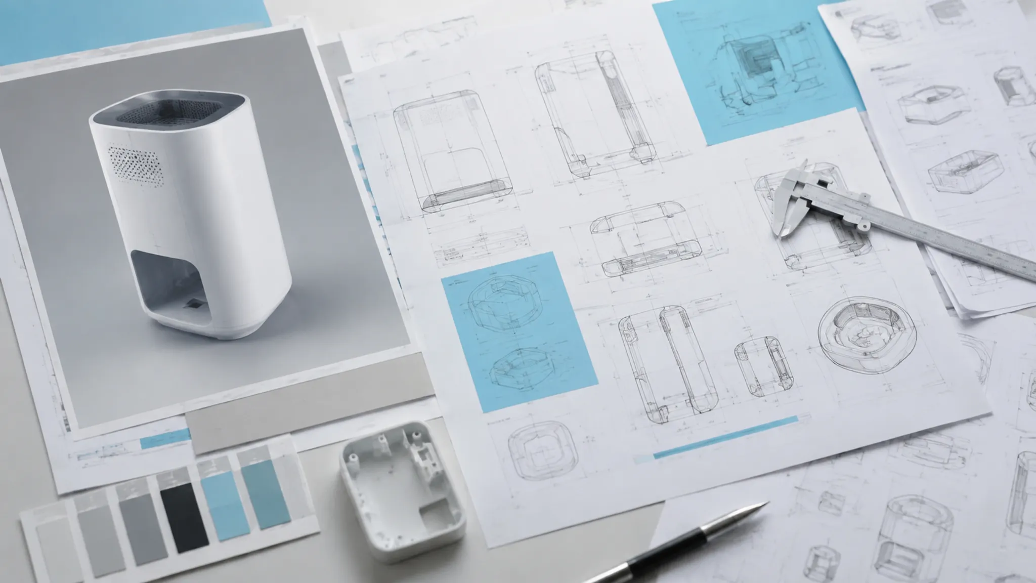
A concept render can make a product direction easy to discuss. It can also make unresolved decisions look settled.
The silhouette may feel correct while the underlying volume remains unclear. A crisp edge break may suggest a material transition that has not been defined. A control may appear reachable from one viewing angle but remain untested in use. These are reasons to carry sharper questions into CAD and engineering review, not reasons to stop visual development.
A useful design handoff checklist connects three layers:
- What the sketch or render visibly communicates.
- What the CAD model, reference material, or documented requirement confirms.
- What still needs review, measurement, analysis, or physical testing.
The aim is to preserve visual intent while making unresolved assumptions visible. A presentation image does not need to answer every engineering question.
What the Checklist Needs to Preserve
A CAD file may contain geometry without the reasoning behind it. A render may communicate proportion and finish while leaving dimensions, interfaces, and behavior undefined. The handoff record should therefore preserve both the selected direction and the limits of what each record supports.
- Current revision and date of the visual direction.
- Source sketches, reference images, CAD files, and material references.
- The selected direction and the alternatives considered.
- The rationale for selecting one direction.
- Critical visual characteristics that should remain recognizable.
- Flexible areas where CAD or engineering constraints may change the form.
- Unresolved assumptions about scale, interfaces, transitions, or use context.
- Known dependencies on components, packaging, mounting, controls, or surrounding space.
- Differences between the latest render and the latest CAD model.
- Questions requiring CAD review, engineering review, source confirmation, or physical testing.
- An owner for each open question.
- The downstream purpose of each file and export.
Handoff language from digital-product workflows can provide useful prompts, but physical-product questions remain primary. A missing interface, unclear datum, or unrecorded spatial assumption can affect the next review differently from a missing software asset.
NASA process guidance is useful here because it keeps assumptions, design rationale, review status, and later verification or validation distinguishable. ASME material supports a related separation between visual intent and formal product definition involving dimensions and tolerances. Neither reference turns a render or checklist into product approval.
Start With Visible Evidence
Before asking what the model should become, describe what the current visual actually shows. Concrete observations give the next reviewer something to trace and compare.

- The silhouette tapers toward the rear.
- The top surface appears flatter than the side surface.
- The edge break reads as a narrow highlight.
- The dark insert appears separated from the main housing.
- The control is visible from the selected three-quarter view.
- The base appears to sit on a horizontal surface.
- The finish changes between the upper shell and lower body.
- The object is shown beside a hand, tool, room, or other scale cue.
These observations are more useful than broad judgments such as “the form feels premium” or “the product looks manufacturable.” The render introduces lighting, camera perspective, surface treatment, and context. Those additions can clarify visual direction while concealing thin walls, sharp transitions, inconsistent radii, or unclear assembly boundaries.
Separate the observation from its interpretation:
| Visible observation | Possible interpretation | Required follow-up |
|---|---|---|
| The side wall appears nearly vertical | The product may have straight-sided massing | Compare section views or CAD |
| A narrow highlight runs around the housing | The edge may have a defined radius or chamfer | Confirm the intended edge break |
| A control appears close to the front edge | The control may be intended for front access | Review reach, clearance, and use context |
| Two surfaces show different roughness | The parts may use different finishes or materials | Confirm the finish direction and material assumptions |
| The base appears stable in the scene | The product may be intended to rest on that plane | Route stability and interface questions to engineering |
The word “may” matters. An image can suggest an intention without documenting a requirement.
Separate Visual Intent From Product Definition
Visual intent concerns what the product should communicate and how its form should be perceived. Product definition concerns the information needed to describe the product precisely for later work. They overlap, but they are not interchangeable.
Visual intent may include:
- Overall silhouette and relative proportion between major masses.
- Perceived visual weight.
- Placement of a seam or transition.
- Visibility of a control or interface.
- Contrast between surfaces.
- The direction of a finish comparison.
- The preferred viewing angle for review.
Product definition may include:
- Dimensions, tolerances, and geometric relationships.
- Material or process requirements.
- Interface conditions.
- Feature information and manufacturing information.
- Structured annotations associated with model geometry.
Model annotations can associate information with geometry, while dimensions, tolerances, notes, and related product information belong to a more formal definition process. Showing a dimension in a presentation image does not establish a complete definition or imply standards compliance.
Use status labels that keep interpretation separate from confirmation:
- Visual direction: communicates intended appearance or proportion.
- Illustrative assumption: improves readability but is not confirmed.
- CAD reference: represented in the current model or drawing.
- Engineering question: requires review against documented requirements.
- Test question: requires measurement, prototype evaluation, or another defined activity.
Compare Sketch, Render, and CAD as Different Records
A sketch, render, and CAD model answer different review questions. The sketch often preserves speed, gesture, and early proportion decisions, but it may contain perspective distortion or incomplete geometry. The render clarifies massing, surface contrast, context, and visual hierarchy, while camera and lighting can change apparent proportion or exaggerate an edge break.
CAD provides a structured geometric reference, but its detail level, feature history, annotations, and revision status determine what it can support. A model made for visual exploration may not contain the information required for engineering review.
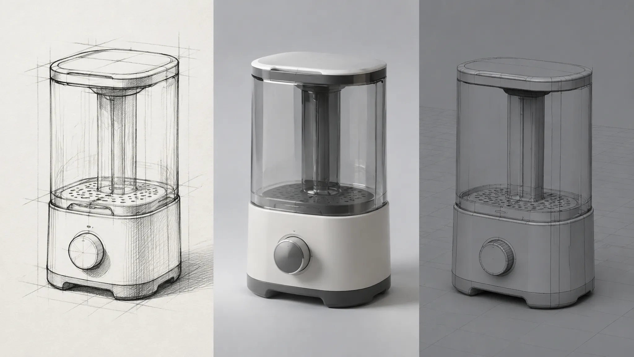
Compare the records using the same view and feature names where possible:
- Is the height-to-width relationship consistent?
- Does the shoulder transition occur in the same location?
- Does the render show a gap, seam, or insert that exists in CAD?
- Is the base footprint represented consistently?
- Does the camera make a surface appear flatter or deeper?
- Are apparent material boundaries actually modeled boundaries?
- Has a component been simplified, omitted, or replaced with a placeholder?
- Which differences are deliberate visual edits?
- Which differences remain unexplained?
The comparison identifies a question. It does not establish which record is correct.
Build a Render-to-CAD Discrepancy Log
A Render-to-CAD Discrepancy Log records differences between presentation imagery and model or reference material. Treat it as an editorial review record, not as a replacement for engineering change control.
| ID | Feature | Render appears to show | CAD or reference shows | Status | Next owner |
|---|---|---|---|---|---|
| D-01 | Upper shell | Continuous soft transition | Transition interrupted near the rear | Observed difference | Design and CAD review |
| D-02 | Front control | Centered on the front face | Location is not defined in the current model | Unresolved assumption | Product and engineering review |
| D-03 | Lower band | Dark, low-sheen surface | Material and finish are not specified | Illustrative finish direction | Materials or engineering review |
| D-04 | Base | Wider footprint than the body | Current CAD footprint is narrower | Observed difference | CAD revision comparison |
Each row should answer five questions:
- What feature can another reviewer locate?
- What does the visual appear to commit to?
- What does the current CAD or reference record show?
- Is the statement observed, inferred, illustrative, or unresolved?
- What review or test can close the question?
Avoid writing “CAD is wrong” unless a documented requirement establishes that conclusion. Use “difference requires resolution” until the relevant record, owner, and criteria are known.
Mark Critical and Flexible Characteristics
Not every visual feature deserves the same handoff priority. A critical characteristic is a feature whose change would alter the selected direction or invalidate an important design decision. Examples may include the main silhouette, the ratio between a display and its housing, the location of a signature transition, or the visibility of a primary control.
A flexible characteristic can change while preserving the intended direction. It may be a secondary fillet, a hidden surface transition, an internal arrangement, or a finish detail outside the agreed review views.
For each characteristic, record:
- Feature name and why it matters visually.
- Reference view or image.
- Acceptable variation, if documented.
- What remains open.
- Who decides when visual intent and an engineering constraint conflict.
Do not invent numeric limits when the project has not defined them. “Keep the shoulder visually continuous from the front three-quarter view” is a visual direction, not a tolerance.
Route Questions by Review Type
A long list of undifferentiated questions slows review. Route each question according to the evidence it needs.
CAD review questions
- Is the current model revision the one used for the render?
- Which surfaces are modeled, and which are placeholders?
- Does the model preserve the intended silhouette across front, side, top, and section views?
- Are key transitions represented as geometry or only implied by lighting?
- Are component boundaries, interfaces, and coordinate references documented?
- What geometry was simplified for visualization?
- Which representation is being delivered, and what downstream purpose does it serve?
- Are source files and referenced components available under the current revision?
CAD review can identify representation differences and missing model information. It does not resolve every performance, material, safety, or use question.
Engineering review questions
- Which visual assumptions depend on dimensions, interfaces, or clearances?
- Which features require formal product definition?
- What requirements govern the critical characteristics?
- Which interfaces must be checked against adjacent components or assemblies?
- Are there conflicts between the selected direction and documented requirements?
- Which assumptions need analysis, prototype inspection, or another verification activity?
- What change could preserve the visual intent if the current direction cannot proceed as shown?
Physical review questions
- Does the proposed form support the intended use context?
- Can users reach, see, hold, or manipulate the relevant areas as assumed?
- Does the physical transition behave as the render suggests?
- Does the selected material or finish produce the intended appearance under actual conditions?
- Which performance or safety questions cannot be answered by imagery?
The exact method belongs to the responsible technical process. The design record needs to make each question visible and traceable.
Document File Format by Downstream Purpose
“Send the CAD file” is incomplete. The useful format depends on what the next person needs to do with it.
- Is the recipient reviewing shape, editing geometry, checking an assembly, creating documentation, or preparing another visualization?
- Is precise geometry required, or is a lightweight visual reference sufficient?
- Does the export preserve relevant structure, units, coordinate information, and associations?
- Are linked references, materials, annotations, or revision identifiers included?
- What software and version must receive the file?
- Which source file remains authoritative?
- What information may be lost during export?
- How will the recipient report a problem with transferred geometry?
Exchange requirements should be agreed according to downstream use. Naming, units, structure, and documented conventions can matter, but adjacent CAD and BIM examples do not establish a universal file-format hierarchy for physical-product work. Record the format decision as a project-specific agreement.
Keep Revisions Connected to Rationale
A revision number tells readers that a record changed. It does not explain why. For each meaningful visual or CAD revision, record what changed, where it changed, why it changed, and which review question prompted it.
Also note whether the change affects a critical or flexible characteristic, which downstream files or views require updates, what remains unresolved, and whether the previous direction was rejected, deferred, or retained as an alternative.
Use matched views when visual direction is under review. Keep camera, crop, scale cue, and lighting consistent where practical. A visual comparison can show that the shoulder is lower, the base is wider, or finish contrast is reduced. It cannot establish that revised geometry meets a dimensional, mechanical, manufacturing, safety, or compliance requirement.
Preserve Rejected Alternatives
The selected direction is only part of the design record. Rejected alternatives explain the boundaries of the decision and help later reviewers understand which differences were intentional.
For each rejected direction, capture a representative view, the characteristic that distinguished it, the reason it was not selected, and whether that reason was visual, contextual, technical, schedule-related, or unresolved. Record any feature worth retaining in a later iteration.
Use inspectable language. “Rejected because the massing felt heavy” is a starting observation. “Rejected because the lower mass dominated the front elevation and reduced the intended separation from the upper shell” gives the next reviewer something to compare.
Use Finish and Context Comparisons Carefully
Finish studies and use-context mockups help when the decision concerns perception. Compare gloss and roughness relationships, contrast between adjacent surfaces, visibility of seams and edge breaks, appearance across viewing angles, scale against familiar objects, and control placement in the intended context.

Label the result as a finish comparison, material direction, or context study. Do not treat the render as proof of material equivalence, durability, tactile behavior, cleanability, optical performance, or production suitability.
A hand or familiar object can clarify apparent size, but perspective and camera distance influence that perception. Use CAD dimensions, documented references, or physical review for conclusions that depend on actual size.
Worked Handoff Example
Consider an illustrative countertop product shown in a front three-quarter render. The image shows a compact rectangular body, a dark lower band, a shallow top transition, and a control near the front-right corner.
The silhouette is clear from the selected angle. The image does not establish the control's actual reach, the band's material, the top transition's radius, or the internal arrangement.
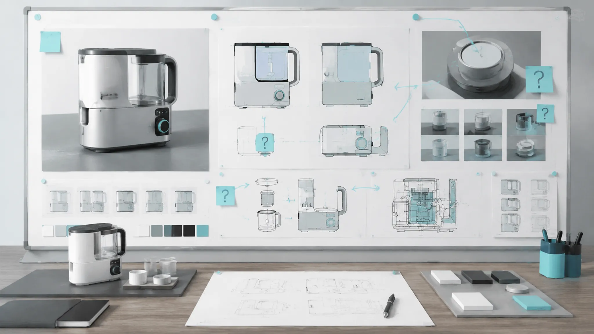
- Selected visual intent: retain the compact massing and separation between the upper body and lower band.
- Critical characteristic: the lower band should read as a continuous horizontal element in the primary views.
- Flexible characteristic: the rear transition may change if the front and side silhouettes remain consistent.
- Observed discrepancy: the render shows a wider base than the current CAD reference.
- Unresolved assumption: the front-right control has not been checked against the intended use context.
- CAD question: is the top transition modeled, or is a highlight producing the appearance?
- Engineering question: which documented requirements govern the control interface and surrounding clearance?
- Finish question: is the dark band a contrast direction or a defined material and finish proposal?
The next record is an updated discrepancy log after CAD comparison, with open interface questions routed to engineering review. The render remains useful because its role is explicit.
Questions to Carry Forward
- What does the selected visual direction commit us to?
- Which visible features are critical to the direction?
- Which features remain illustrative?
- Which assumptions have not been checked against CAD?
- Where do sketch, render, CAD, and reference files disagree?
- Which differences are deliberate, and which need a revision decision?
- What information is missing from the current source files?
- What is the downstream purpose of the delivered file?
- Which questions belong to CAD review, engineering review, or physical testing?
- What alternative was rejected, and why?
- Who owns each unresolved question?
- What revision should be treated as current after review?
A design handoff checklist does not remove uncertainty. It gives uncertainty a location, a description, and a next owner.
Frequently Asked Questions
What is the purpose of a design handoff checklist?
It preserves the selected visual direction while documenting source files, revisions, rationale, assumptions, open questions, and ownership. It helps the next reviewer separate what the concept shows from what remains to be confirmed.
Should the render or CAD model be the primary reference?
The answer depends on the review question and the project's documented source-of-truth agreement. A render may guide visual direction, while CAD or formal product-definition records may govern geometric and engineering questions. Record that distinction instead of assigning every question to one file.
What should a CAD engineering handoff include?
Identify the current revision, source files, downstream purpose, key visual decisions, known differences, unresolved assumptions, dependencies, and questions routed to CAD or engineering review. Exact file, annotation, dimension, and documentation requirements remain project-specific.
How should sketch-to-CAD spatial issues be recorded?
Name the feature, describe the visible assumption, compare it with the current CAD or reference record, label the difference as observed or inferred, and assign a next review. An unexplained difference is not evidence that either record is correct.
Is a photorealistic render enough for engineering review?
It can support discussion of visual direction and help identify questions. It is not sufficient evidence for dimensions, mechanisms, materials, ergonomics, manufacturing, safety, compliance, or performance.
Why keep rejected alternatives?
Rejected alternatives preserve design rationale. They show which characteristics were considered, why a direction was selected, and which ideas should not be reopened without new information.
What belongs in a visual intent note for CAD handoff?
Describe the silhouette, proportion, massing, transitions, edge breaks, visible interfaces, finish relationships, scale cues, and preferred review angles. Mark each item as critical, flexible, illustrative, or unresolved.