Form and Proportion Preflight
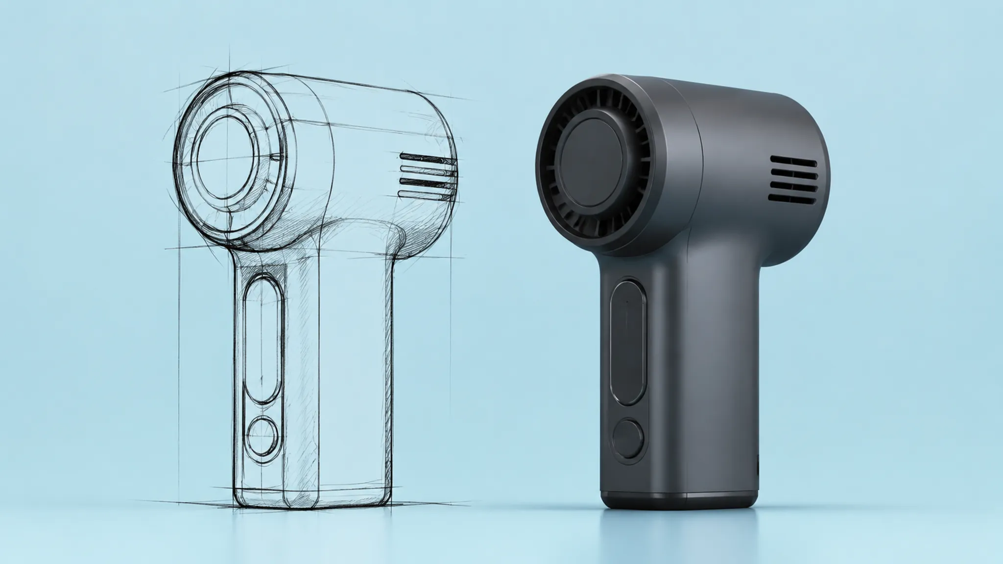
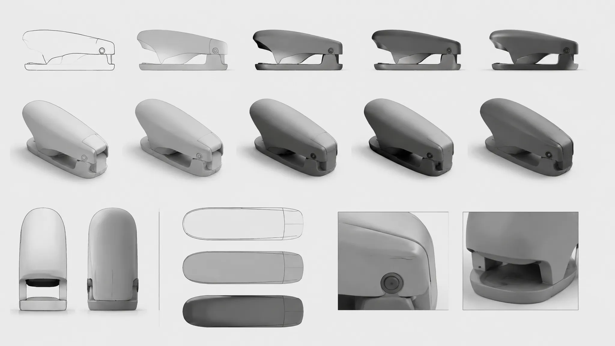
A product sketch and a concept render can describe the same direction while producing different judgments. The sketch may commit to a silhouette, massing relationship, or transition. The render then adds perspective, lighting, finish, context, and post-processing.
A useful render proportion check asks whether the intended form remains consistent across those representations. It does not ask which image looks more finished. A convincing render can clarify form, but it can also make an unresolved assumption appear settled.
Separate the sketch commitment from the render treatment
A sketch provides an incomplete but direct record of visible design intent. Line placement, contour, construction marks, and shading indicate which edges, planes, transitions, and details the designer chose to communicate.
The sketch shows a visual commitment. It does not necessarily define every dimension, mechanism, or hidden relationship.
A rough drawing may leave depth ambiguous while making the overall direction easy to compare. A cleaner perspective sketch can add edge hierarchy, surface curvature, or detail thickness. Each addition changes what the reviewer can infer.
Start the comparison by recording what remains stable:
- Overall silhouette and height-to-width relationship
- Position and apparent size of major volumes
- Relative thickness of housings, handles, bezels, or controls
- Direction and strength of the main contour
- Placement of openings, seams, buttons, and visible details
- Location of major transitions and edge breaks
- Relationship between the primary body and attached components
Keep observations separate from interpretations. “The upper body occupies less of the outline” describes a visible relationship. “The product will be easier to hold” reaches beyond the image and belongs in another review.
Identify what the render introduces
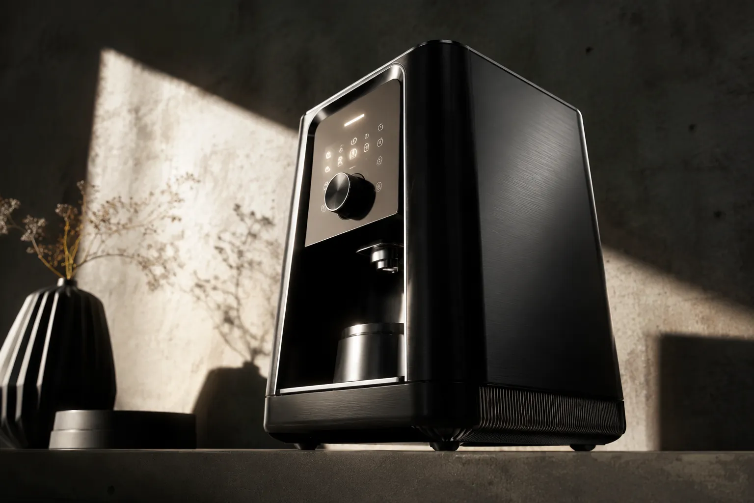
The render adds a chosen viewing condition. Camera position, perspective, light direction, shadow density, surface reflectance, texture, background, and surrounding objects all influence how the form is read.
A product sketch and render comparison therefore needs two questions:
- What changed in the represented product form?
- What changed in the conditions used to view it?
A close camera can enlarge a foreground feature relative to the body. A low viewing angle can make the body appear taller. Dark material may suppress a transition, while a bright highlight can make shallow curvature appear stronger. A cast shadow adds grounding and visual mass without adding dimensional information.
These effects are not automatically errors. They become review problems when image treatment is mistaken for product evidence.
Use language that can be checked against the images:
- “The render introduces stronger perspective around the front edge.”
- “The lighting suppresses the transition on the side wall.”
- “Material contrast separates the control area from the housing.”
- “The context supplies a scale cue, but the size relationship remains unverified.”
- “The comparison suggests a proportion difference that should be checked against the model.”
Run silhouette checks between sketches and renders
The silhouette is the first comparison layer because it remains readable after internal detail and surface treatment are removed. It describes the visible outer boundary from one viewing angle.
Do not expect two outlines to be identical. Isolate differences that change the character or balance of the product.
Compare overall massing
Read the main body as one volume before inspecting details. Determine whether it appears longer, taller, flatter, narrower, or more tapered in either representation.
Massing carries many of the strongest proportion decisions. Realistic material cannot compensate for a camera or crop that communicates a different body relationship.
Measure secondary volumes against the body
Inspect handles, collars, bases, lids, feet, screens, and other attached forms relative to the primary mass. Do not judge them in isolation.
A secondary volume may appear heavier because of a dark edge, cast shadow, or high-contrast seam. Record that impression, but do not treat it as evidence of actual thickness.
Trace the contour rhythm
Follow changes along the outer boundary instead of comparing only its endpoints. Small shifts in bulges, tapers, shoulders, and corners can alter the balance of the whole product.
Internal contour lines may make curvature easier to read even when the outer silhouette has not changed. Note that as a representation difference.
Locate edge breaks and transitions
Look for where a plane changes direction, a radius begins, or one volume meets another. Gradients and reflections may clarify that transition. Dark finishes or shallow lighting can conceal it.
Record whether the transition is visible, absent, or ambiguous. Visibility does not establish the underlying geometry.
Check the apparent thickness of details
Buttons, knobs, vents, rims, and small controls may appear flat in a sketch and dimensional in a render. Compare their relative scale and placement, then flag any thickness that affects the direction under review.
Research on concept representation distinguishes features such as construction lines, contour lines, edge clarity, shading, cast shadows, and material cues. These categories provide useful inspection vocabulary, not a universal scoring system or professional preflight standard.
Control the viewing angle before judging proportion
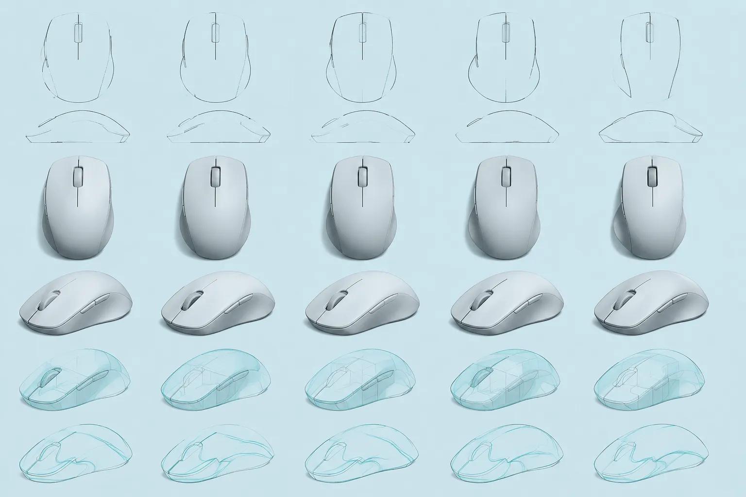
A proportion judgment belongs to a viewing condition. Change the angle and the available visual evidence changes with it.
Match the primary orientation, crop, eye level, and visible faces as closely as practical. A different view can reveal unresolved form, but it cannot serve as a direct before-and-after comparison without qualification.
Perspective enlarges near features, shortens receding planes, and shifts attention toward the foreground. A controlled or orthographic view can help isolate relative form. It still does not prove dimensional accuracy.
Record the comparison conditions:
- View name or direction
- Approximate camera height or eye level
- Visible product faces
- Crop and image ratio
- Presence or absence of perspective
- Changes in camera or object orientation
- Reference points shared by the sketch and render
When the views cannot be matched, label the comparison as directional. Send dimension-sensitive questions to CAD or another documented geometric view.
Distinguish visual proportion from dimensional questions
A useful preflight does not remove uncertainty. It sorts each open question into the review that can answer it.
| Review question | What can be discussed now | Where confirmation belongs |
|---|---|---|
| Does the top volume dominate the body? | Visible balance across matched views | CAD when the actual ratio matters |
| Does the side profile retain its taper? | Silhouette and contour continuity | Another geometric view or model check |
| Does a control appear oversized? | Apparent scale relative to the housing | Dimensional and use review |
| Is a transition intentional? | Its visibility and treatment in each image | CAD or a documented design reference |
| Will a mechanism have enough clearance? | The image can only identify the open question | Engineering review |
Photorealistic treatment does not establish dimensions, mechanisms, ergonomics, material performance, manufacturing feasibility, safety, compliance, market acceptance, or reuse permission. Those conclusions require their own records and review methods.
Test lighting and material effects
Lighting is part of the representation, not a neutral window onto the product. A broad gradient can reveal curvature. A sharp highlight may create a strong edge cue. Contact shadows can join two parts visually, while a dark recess can exaggerate their separation.
Material treatment has a similar effect. Gloss, roughness, reflectance, texture, and color contrast can reveal or suppress transitions. A reflective body may imply a plane change more strongly than its contour supports.
Where the workflow permits, compare the concept render using reduced presentation treatment:
- Silhouette or flat outline
- Neutral surface value
- Reduced texture
- Lower contrast
- Alternate light direction
- Front, side, and rear views
- A crop without contextual objects
These are comparison aids. A concern is more likely to belong to the represented form when it remains visible after major presentation effects are reduced. If it disappears with a change in light, material, crop, or camera, record it as an image-dependent impression.
Separate product form from context and scale cues
A tabletop, hand, room, vehicle interior, or adjacent object can indicate orientation and approximate use context. It does not confirm scale unless the relationship is documented.
Context also changes visual priority. A nearby large object can make the product appear smaller. A low camera can add apparent mass. A clean background can make the silhouette more prominent than it would be in a use scene.
Review the scene in layers:
- Which form information comes from the product boundary?
- Which scale impression comes from surrounding objects?
- Does the context obscure an edge or transition?
- Has the crop made one feature unusually prominent?
- Is the scene illustrative, proposed, or based on a documented use condition?
Label illustrative context accordingly. Do not use it as evidence of user experience, product suitability, or market response.
Use a five-pass render proportion check
Pass 1: Compare the unstyled outline
Place the sketch and render side by side. Reduce attention to finish and inspect the outer boundary, major masses, and visible proportion relationships. Record only what can be seen.
Pass 2: Compare internal structure
Inspect contours, edge breaks, seams, controls, openings, and transitions. Mark details that are clearer, newly introduced, or no longer visible. A missing line does not necessarily indicate a missing feature.
Pass 3: Isolate representation effects
Review camera, perspective, lighting, material, shadows, background, and post-processing. Name the effect that strengthens or suppresses each interpretation.
Pass 4: Add another view or reference
Use a second view, controlled projection, CAD snapshot, or approved source image when the question concerns depth, alignment, or placement. Multiple views can constrain interpretation, but they do not by themselves confirm the model.
Pass 5: Route open questions
- CAD review for dimensions, alignment, and geometric relationships
- Engineering review for mechanisms and implementation questions
- Source confirmation for provenance and asset records
- Material review for appearance assumptions requiring documented samples
- Physical review for questions images cannot settle
Preserve the visible issue in the handoff. “The side transition disappears under the current light, and its intended radius is not documented” gives the next reviewer more to act on than a general reaction to the render.
Worked example: one image, three different findings
Consider a hypothetical handheld product shown as a loose perspective sketch and then as a polished concept render. The sketch shows a compact body, narrow top section, and handle close to the rear contour.
The render uses a low camera, dark body finish, bright control panel, and cast shadow. The handle now appears thinner, the top appears taller, and the control panel attracts more attention.
These are separate findings. The handle difference may come from silhouette or camera position. The taller top may be a perspective effect. The control panel is likely receiving emphasis from contrast and finish.
A matched second view or neutral treatment can test the first two interpretations. CAD can determine whether the underlying ratios changed. The comparison alone cannot.
Record what should move forward
The preflight should leave a compact record that can travel with the selected direction:
- The sketch and render versions compared
- Matched or unmatched viewing conditions
- Stable visual relationships
- Visible proportion changes
- Camera, lighting, material, context, and post-processing effects
- Open dimensional assumptions
- The next view, source record, CAD review, or physical check required
- The workstream responsible for each open question
Which proportion decision is supported by both representations, and which impression appears only after the render treatment?
This preflight supports a structured visual review, not a complete product-design standard. Decide which form relationships remain consistent now. Record image-dependent impressions separately, then route dimensional and physical questions to the artifact that can resolve them.
Sources
- The effect of sketch and render quality and design experience on concept evaluation in engineering design
- Design Drawing Parameters and its Impact on the Evaluation of Design Proposals
- Beyond procedural approaches to designing: a framework for supporting students’ hierarchical thinking through their representational journeys
- Utilizing Visual Illusions To Identify and Understand Perceptual Discrepancies in Product Design
- 3D modeling with silhouettes