
Form and Proportion Comparisons
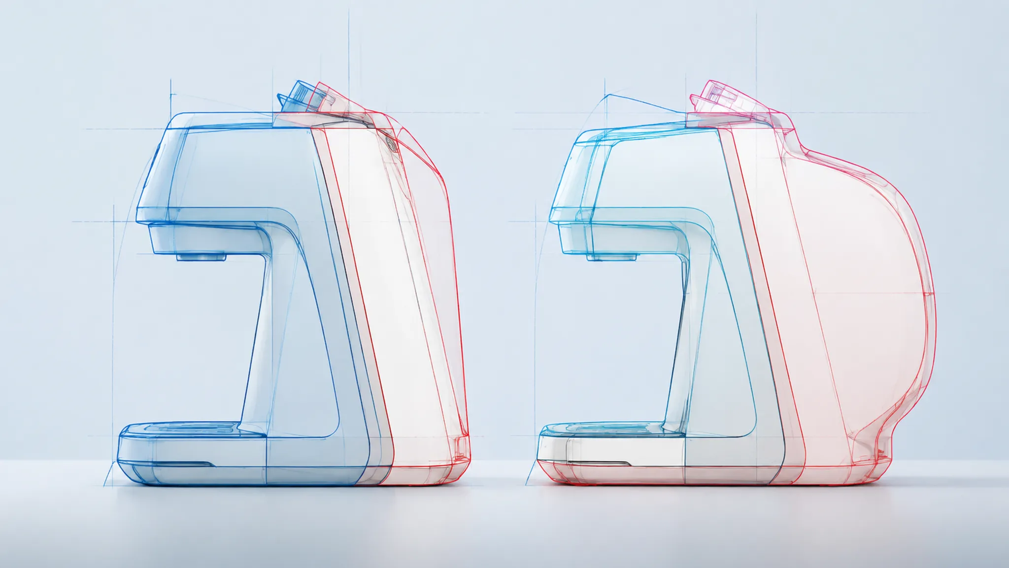
Two product directions can share the same styling language and still communicate different proportions. One may carry more mass above the centerline, extend the base, tighten a shoulder transition, or move a control toward the edge.
A silhouette overlay makes those differences inspectable. It can show where outer contours, major masses, feature placement, and transitions diverge. It can also reveal when a sketch and concept render no longer communicate the same direction.
The overlay is image evidence, not dimensional proof. Perspective, crop, alignment, and scale cues can create apparent differences that remain unconfirmed. Record what the comparison shows beside the assumption that still needs checking.
More specific pages
These pages continue the topic in smaller, more specific directions.
Using Silhouette Overlays to Compare Product Proportions
A silhouette overlay places two or more product outlines in one comparison view. Each direction remains distinguishable through line weight, color, opacity, or sequential display. The purpose is to isolate form relationships that separate images make harder to judge.
Start with visible differences rather than an overall verdict. A useful observation might state that one direction rises earlier at the top contour, extends farther at the rear, narrows more sharply through the waist, or places a control cluster higher against the main body.
- The top contour rises earlier in one direction.
- The rear mass extends farther from the apparent center.
- The base occupies more of the visible product width.
- A shoulder transition begins sooner or resolves more abruptly.
- A control cluster sits higher relative to the surrounding body.
- A corner break changes from gradual to clearly segmented.
These are observed image differences. They do not establish physical dimensions, internal volume, component fit, balance, or performance.
| Review level | Appropriate statement | What remains open |
|---|---|---|
| Observed | Direction B extends beyond Direction A at the rear contour. | The physical extension and its measurement. |
| Comparative | The rear mass occupies more of the visible silhouette. | Internal volume and component space. |
| Inferred | Direction B may read as more rear-weighted from this view. | Balance, stability, or handling. |
| Unresolved | The difference may be affected by perspective or alignment. | Which source depicts the intended geometry. |
| Routed | Confirm the rear extent in CAD or a dimensioned view. | The result of that later verification. |
This separation turns a subjective reaction into a reviewable statement. It also prevents a detailed render from carrying more authority than its source supports.
Start With Comparable Source Views
A product proportion comparison depends on the relationship between its source images. When the views are not comparable, the overlay can reveal drawing differences, but it cannot cleanly isolate design differences.
Record the setup before interpreting the contour:
- Source type: rough sketch, refined drawing, concept render, model view, or photograph.
- Viewing angle: front, side, rear, top, or three-quarter.
- Camera condition: orthographic, perspective, or unknown.
- Alignment basis: base plane, centerline, axle, control axis, or another visible anchor.
- Scale basis: known dimension, common feature, bounding height, bounding width, or apparent fit.
- Crop: full product, partial view, or uneven framing.
- Image status: documented reference, concept study, generated preview, or source requiring confirmation.
- Known distortion: lens perspective, sketch construction, image warp, or unknown projection.
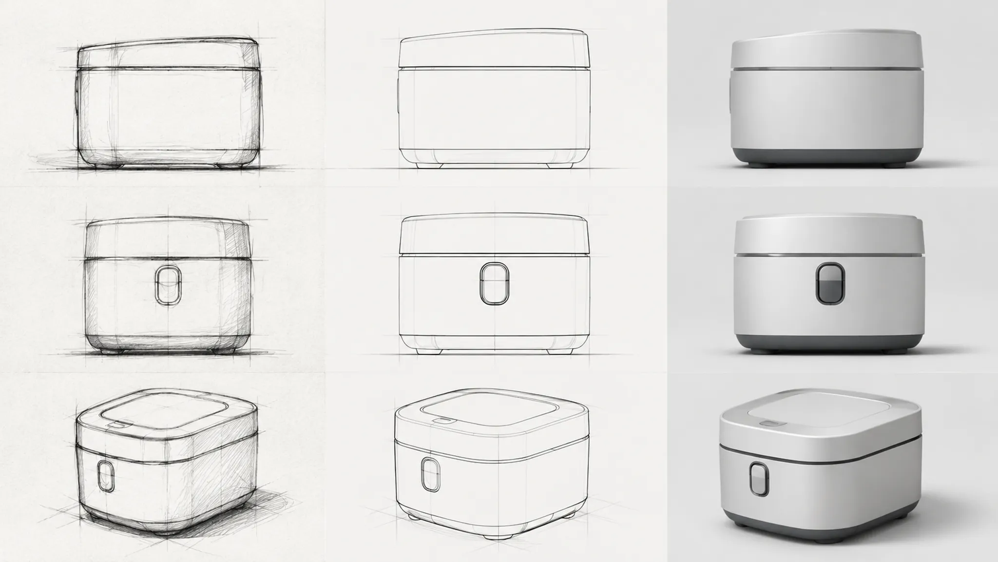
An overlay made from a side sketch and a three-quarter render mixes contour change with view change. It may show that the render presents a fuller front mass, but it cannot establish whether the design itself became fuller. The viewing angle remains an unresolved assumption.
Scaling introduces a related problem. Matching overall height can make a width difference visible, but it can also conceal a change in intended total size. The review record should state which relationship was held constant and why.
Choose an Alignment Basis That Fits the Decision
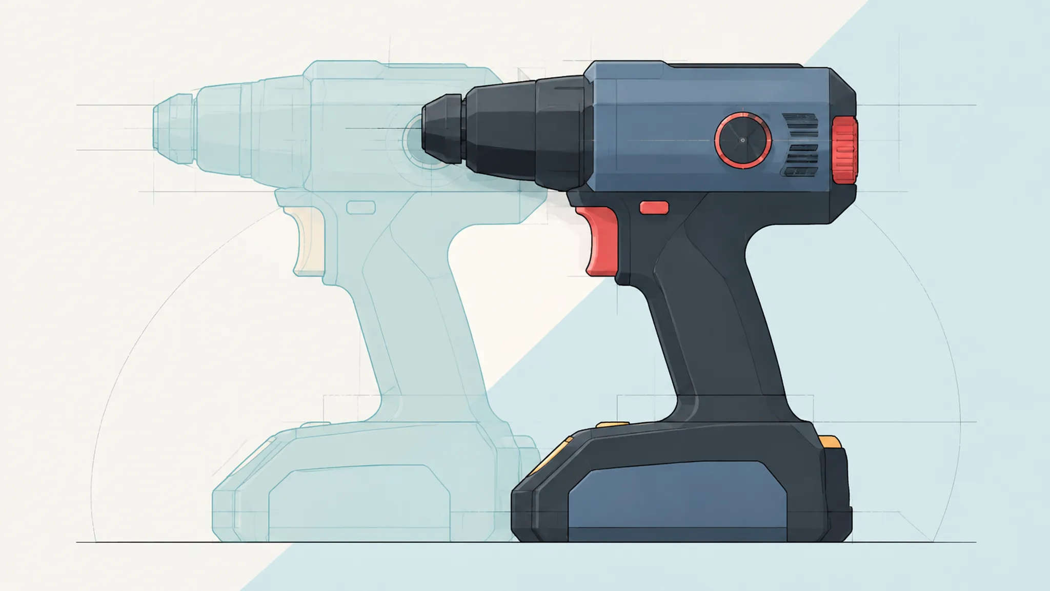
Alignment is not a neutral setup step. It determines where differences accumulate and influences what reviewers notice first.
Base alignment
Aligning directions to a visible base plane supports comparison of total height, upper massing, and contact relationships. It helps when the decision concerns stance or the distribution of form above the base.
It becomes less informative when the base itself changed. A thicker foot, recessed contact area, or altered support geometry may shift the apparent body position.
Centerline alignment
A shared vertical or horizontal centerline can expose asymmetric growth. It helps show whether one direction expands evenly or places more mass toward a particular end.
Document the centerline rather than guessing it. A bounding-box midpoint is not necessarily a product datum or functional axis.
Feature alignment
A stable feature can anchor the comparison when its relationship to the surrounding body is under review. Examples include a wheel center, hinge axis, display center, handle attachment, or repeated control position.
This method makes changes around the anchor easier to see. It can also push source disagreement toward the opposite end of the product. That accumulation should not be mistaken for a single local revision.
Bounding alignment
Matching overall height, width, or bounding area supports a normalized comparison of shape. It answers a narrow question: how do the contours differ when one visible extent is held constant?
Normalization removes information about absolute scale. Use it for relative form comparison, then return to a view with documented scale information before making dimensional decisions.
When the decision is unclear, prepare more than one alignment. Agreement across a base-aligned and feature-aligned view strengthens the visual observation. Disagreement identifies an assumption that needs verification.
Read Product Proportion From Large Masses to Small Features
Compare the whole silhouette before examining surface detail. Research on product-appearance comparison supports attention to feature proportion, orientation, shape, and the limits of reducing three-dimensional products to two-dimensional representations. For the review, the practical sequence is broad form, massing, feature placement, then transitions.
Compare the outer contour
Trace where the silhouettes separate, then describe the direction of each departure:
- Taller or lower.
- Wider or narrower.
- Longer or shorter in the image.
- Fuller or flatter.
- More tapered or more parallel.
- More continuous or more segmented.
Avoid summarizing the result as “more balanced” or “better proportioned.” Those judgments hide the evidence. Identify the contour region that produced the reaction.
Check image resolution before tracing. A soft shadow, reflection, chamfer, or background edge can be mistaken for the product outline. Mark uncertain boundaries instead of converting them into claimed geometry.
Compare massing relationships
Divide the visible form into major masses that fit the actual product: a base, central body, upper housing, handle, interface block, or projecting feature.
- How much visible width does the base occupy?
- Where does the upper mass begin?
- Which volume dominates the silhouette?
- Does one direction separate the masses more clearly?
- Does a projection appear integrated or attached?
- Is the visual center displaced toward one end?
These remain two-dimensional observations. Visible area does not establish internal capacity, actual volume, weight distribution, or component space.
Compare feature placement
Once the larger masses are understood, compare visible features against stable image references such as the bounding contour, a centerline, or another feature.
A control may appear higher because the body became shorter, because the control moved, or because the image was scaled differently. The overlay exposes the changed relationship. It does not identify the cause unless the source documentation does.
Compare transitions and edge breaks
Transitions often explain why two directions feel different despite similar bounding dimensions. Inspect shoulders, necks, corner breaks, tapers, undercuts, and changes in curvature.
Ask where the transition starts, how long it remains visible, and whether it resolves gradually or sharply. Lighting or finish may suppress an edge in a render, so cross-check the transition against a line drawing or another view.
Separate Form Change From Presentation Change
The sketch may establish a broad silhouette while leaving perspective, surface continuity, and feature depth unresolved. A concept render introduces those cues. It may also introduce decisions that were never approved.
Classify the possible source of each difference:
- Design revision: the underlying direction intentionally changed and the design record supports that change.
- Interpretation: the render resolves an ambiguous sketch feature.
- Projection: camera angle or perspective changes the apparent proportion.
- Presentation: lighting, finish, shadow, or background alters the perceived boundary.
Consider a hypothetical tabletop device. The sketch shows a low body with a centered upper housing. The render makes the housing appear taller and shifts its highlight toward the rear. The overlay shows the rendered housing rising above the sketch contour, but the rearward emphasis may come from shading rather than geometry.
Record the finding in separate layers:
- Observed: The rendered housing extends above the sketch contour.
- Inferred: The render presents a more top-heavy massing relationship.
- Unresolved: The sources use different projection, and the sketch has no documented housing height.
- Action: Confirm the intended profile in a matched view and check the height in the dimensional model.
The render adds a decision the sketch did not make. Keep that question open until the next artifact can answer it.
Check Viewing Angle and Scale Cues
A silhouette changes with viewpoint. A small rotation can expose a side surface, shorten a projected length, move overlapping features, or change where a transition appears to begin.
Research comparing rendered, rotating, immersive, and physical presentation conditions indicates that viewpoint, distance, scene context, and available sensory cues can affect how people perceive product size and spatial relationships. For an overlay, the practical conclusion is narrow: treat proportion as a property of the comparison view until it is checked elsewhere.
- One image reveals more of a side or top surface.
- Parallel edges converge differently.
- Near features appear enlarged in only one source.
- The horizon or camera height is inconsistent.
- One product sits beside a familiar object while the other is isolated.
- Shadows imply different contact planes.
- Cropping removes a feature that could provide a scale cue.
- A wide-angle view enlarges the nearest mass.
A hand, room, vehicle wheel, control, or support surface can help viewers interpret apparent size. It does not supply a dimension unless its size and relationship to the product are documented.
When matched source views are unavailable, use the overlay as a diagnostic of presentation disagreement. Route the proportion question to a controlled view rather than treating the image difference as a confirmed product change.
Build a Product Silhouette Comparison Workflow
A useful review sequence needs a controlled question and a traceable record. The software may vary; the comparison logic should remain visible.
1. Define the review decision
Write one sentence explaining what the comparison must clarify:
Compare whether Direction B preserves the low upper-body proportion established in the approved sketch.
A focused question prevents the overlay from becoming an open-ended search for differences.
2. Audit the source images
Check view, projection, crop, resolution, scale cues, and source status. Record any mismatch that could influence interpretation. Preserve the original when an image must be rotated, warped, or rescaled, and document the adjustment.
3. Select the alignment basis
Choose an anchor connected to the review decision. State what is held constant and why. Where the result depends heavily on that choice, prepare a second alignment and compare the assumptions it exposes.
4. Trace defensible boundaries
Follow the visible outer contour first. Add internal feature lines only when their boundaries can be identified consistently in both sources. Keep uncertain areas marked as uncertain.
5. Compare in layers
- Overall bounding proportion.
- Outer contour.
- Major massing.
- Feature placement.
- Transitions and edge breaks.
- Scale cues and use context.
- Surface details that may alter boundary perception.
6. Classify each finding
Label material findings as observed, inferred, or unresolved. Label hypothetical and generated concept previews as such. A useful finding connects evidence to a consequence:
The overlay shows an earlier shoulder rise in Direction B. This suggests a larger upper mass from the side view. Camera equivalence remains unconfirmed, so the shoulder profile should be checked in a matched model view.
7. Record the next action
| Unresolved question | Next evidence |
|---|---|
| Is the apparent length difference physical? | Dimensioned drawing, documented specification, or CAD measurement. |
| Does the feature occupy the intended position? | Matched model view and feature-location record. |
| Does the control support the intended reach? | Ergonomic review and physical evaluation. |
| Does the internal arrangement fit? | CAD layout and engineering review. |
| Can the form be produced as intended? | Manufacturing review based on defined geometry and process. |
| Does the material behave as the render suggests? | Material specification, sample, or appropriate testing. |
| Is the source image available for the intended use? | Provenance record and rights confirmation. |
The overlay closes the visual comparison. It does not close every downstream question.
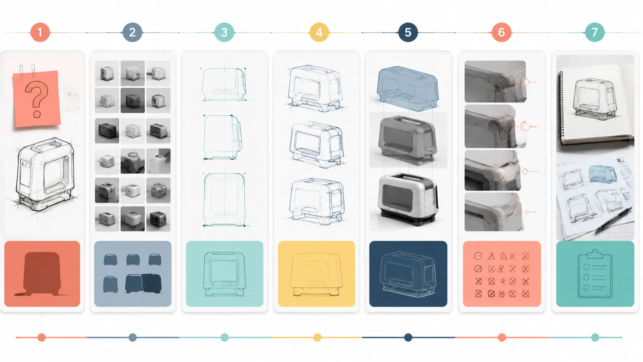
Use Side-by-Side Views With the Overlay
An overlay exposes contour disagreement, but it compresses context. Dense intersections can become difficult to read, and transparency may obscure which line belongs to which direction.
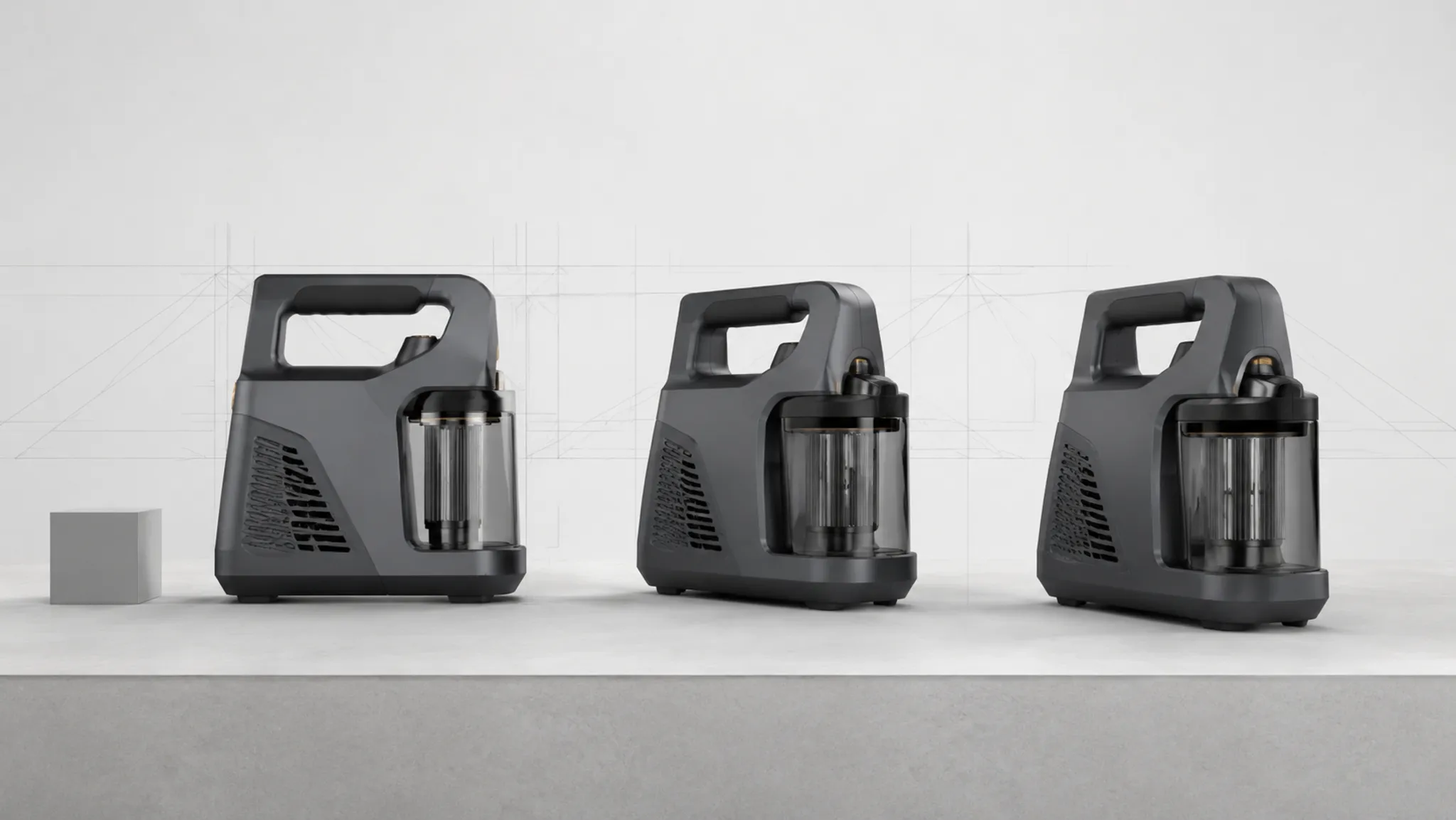
A stronger comparison sheet uses three coordinated views:
- Side by side: preserves each direction as a coherent product image.
- Overlay: isolates positional and contour differences.
- Detail crops: clarify a transition or feature relationship without enlarging the entire page.
Keep camera labels, alignment basis, and concept identifiers visible. Use consistent colors across every view. When an outline changes meaning between panels, reviewers may attribute the wrong contour to the wrong direction.
Alternating or sequential display can help when contours are crowded. Its value is diagnostic: it allows reviewers to isolate where one boundary departs from another.
Common Product Proportion Review Mix-Ups
Matching the bounding box is treated as matching scale
Two silhouettes can share the same overall height while representing different intended sizes. Bounding alignment normalizes the images for shape comparison. It does not confirm common physical scale.
More detail is treated as more certainty
A refined render adds lighting, materials, reflections, and surface transitions that a rough sketch may omit. These additions can make the image feel more authoritative while concealing an unsupported proportion decision.
Visible area is treated as volume
A larger two-dimensional region suggests a different massing relationship from that view. It does not establish three-dimensional volume, capacity, or weight.
One view is treated as the complete form
A side silhouette may hide width, depth, undercuts, and overlapping features. Check the interpretation against another view before recording a whole-product conclusion.
Feature movement is assumed when the body changed
A control can shift relative to the contour even when its model position is unchanged. The surrounding body may have grown, narrowed, or rotated. Compare the feature with its reference frame.
A presentation cue is recorded as geometry
Highlights, cast shadows, tonal boundaries, and material breaks can resemble physical edges. Trace geometry only where the source makes the boundary defensible.
Visual agreement is treated as downstream confirmation
A clean overlay can show that two images communicate closely related silhouettes. It does not answer dimensional, physical-use, mechanical, material, manufacturing, compliance, market, or source-rights questions.
Product Proportion Review Limitations
Public research directly addressing silhouette overlays for early product-proportion review remains narrow. The most relevant appearance-comparison work supports examining feature proportion, orientation, shape, and transitions while identifying the limits of tracing image features and reducing three-dimensional products to two-dimensional representations.
Studies of product perception across rendered, rotating, virtual, and physical presentation conditions add a broader boundary. They support caution around viewpoint and presentation context, but they do not establish a universal overlay procedure, numerical acceptance threshold, dimensional accuracy, physical-use suitability, software performance, production feasibility, market preference, or source-use permission.
Keep the overlay within its declared scope. It is suited to questions such as:
- Where do the visible contours diverge?
- Which mass appears larger relative to the whole?
- Has a feature moved within the image?
- Does a transition begin earlier or resolve differently?
- Which source or presentation assumption could explain the difference?
- What evidence must be checked next?
When the decision depends on actual dimensions or physical use, move beyond the overlay to documented geometry, qualified review, source confirmation, or physical evaluation.
Documenting Product Design Review Actions
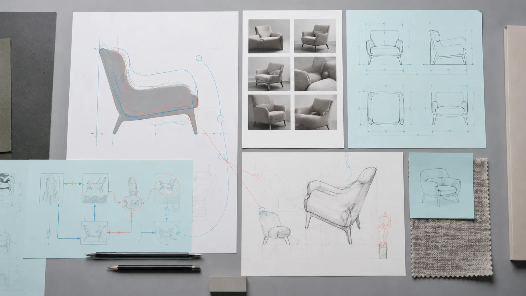
A comparison becomes useful to the next stage when another reviewer can reconstruct how the judgment was made. Preserve the source images, comparison view, setup, findings, and open questions together.
A compact review record can include:
- Decision under review: the proportion relationship being compared.
- Sources: each sketch, render, study, or model view by version and status.
- Comparison setup: viewpoint, projection if known, crop, scale basis, alignment anchor, and image adjustments.
- Observed evidence: visible contour, massing, placement, and transition differences.
- Interpretation: what each difference suggests about the concept's visual character.
- Unresolved assumptions: uncertain camera conditions, boundaries, dimensions, or source decisions.
- Review outcome: which direction moves forward, which relationship needs revision, or why the decision remains open.
- Verification route: the drawing, model view, specification, review, source check, or physical evaluation required next.
A concise action might read:
Preserve Direction A's lower shoulder line. Revise the next preview to match the documented side-view camera and base alignment. Confirm shoulder height and control position in CAD before carrying the proportion into later presentation views.
That note distinguishes visible design intent from evidence still required. It gives the next contributor a specific relationship to preserve.
What a Defensible Comparison Should Leave Behind
A useful product proportion comparison does not need to settle every aspect of the product. It needs to make the visual decision traceable.
- The product directions and source versions compared.
- The alignment basis, viewpoint, and scale cues used.
- The locations where outer contours diverged.
- The relationships among major masses.
- The features or transitions that changed.
- The statements classified as observed or inferred.
- The assumptions that remain untested.
- The document, review, or test assigned to each open question.
The comparison is complete when reviewers can point to the visible difference, explain its relevance to the concept direction, and carry a clear record into the next stage. Decide the visual relationship now; route dimensional, physical-use, material, production, and source questions to the evidence that can address them.
Sources
- A method for exploring similarities and visual references to brand in the appearance of mature mass-market products
- Cognitive differences in product shape evaluation between real settings and virtual reality: case study of two-wheel electric vehicles
- Perceiving Design Features in New Interaction Environments: Comparing Rendered Images, 360° Rotation, AR, Immersive and Non-Immersive VR, and Real Product Interaction
- Comparing Virtual Reality and Desktop Interface for Reviewing 3D CAD Models