
Using Silhouette Overlays to Compare Product Proportions
A silhouette overlay makes proportion differences easier to review when both product views use the same viewing direction, projection type, scale treatment, and alignment.
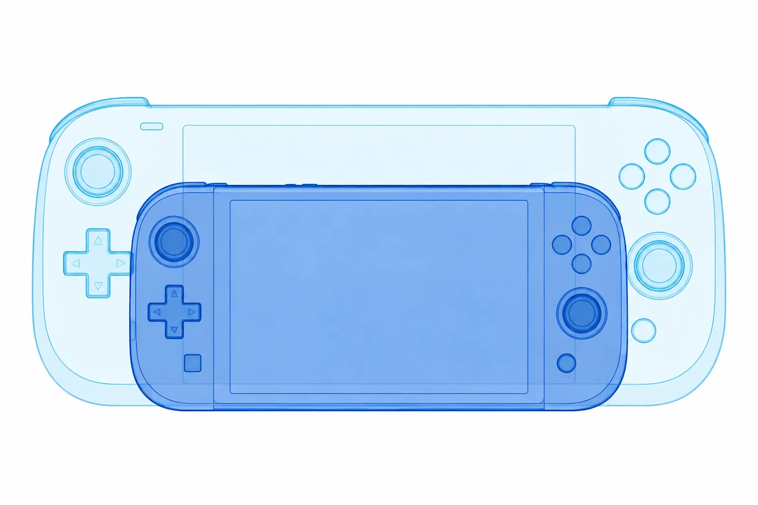
The comparison may show that one concept appears taller, wider, heavier, more tapered, or differently balanced. It does not establish exact product dimensions. Treat the result as a visual comparison that directs the next review question.
What a Silhouette Overlay Can Show
A silhouette reduces a product image to its outer contour and overall massing. This makes broad relationships between height, width, taper, feature position, and edge transitions easier to inspect.
In an illustrative comparison between two handheld product concepts, the overlay might reveal:
- A taller upper body
- A wider base or shoulder
- A stronger taper toward one end
- A different height-to-width relationship
- A shifted control, opening, panel, or display
- More visible mass on one side
- A sharper or softer outline transition
- A different corner or opening shape
These are observations from the image. They suggest how the forms may be perceived under the selected view conditions, but they do not describe hidden geometry or explain why the difference exists.
Product-form research commonly separates visible appearance into variables such as proportion, orientation, and shape. That distinction turns a reaction such as “this version feels heavier” into an inspectable question: Is the body wider, is the upper mass larger, or has the taper been reduced?
The silhouette exposes a visible difference. Another form of evidence may be needed to identify its cause.
A Controlled Silhouette Overlay Workflow
The overlay becomes useful when its conditions are recorded before the result is interpreted. Start with comparable views rather than placing any available images on top of each other.
1. Select comparable views
Match the general view relationship. Compare a front view with another front view, and a side view with another side view.
Record the source and status of each image. A concept render, sketch, photograph, and CAD export carry different kinds of visible information. Label a generated preview as a concept preview rather than treating it as a product record.
A perspective render and an orthographic silhouette should not be treated as equivalent evidence conditions. Their contours may differ because of projection rather than product form.
2. Match the viewing condition
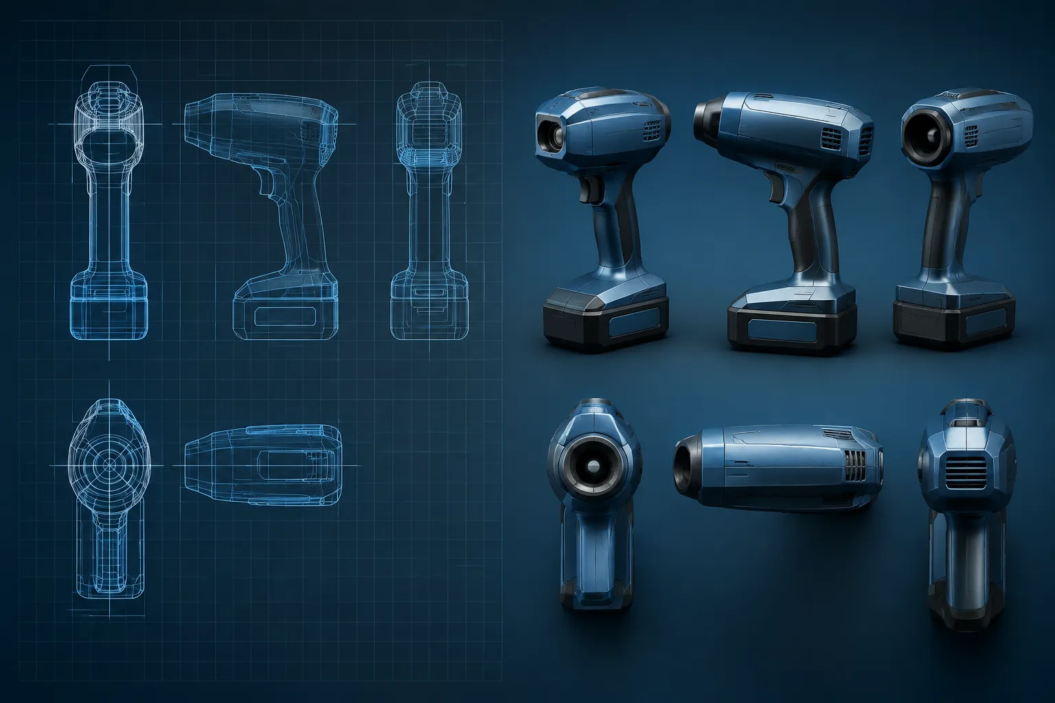
Projection describes how three-dimensional form is represented in an image. ISO 5456-2 provides terminology for projection methods and helps distinguish orthographic from perspective representation.
Keep the projection type and viewing direction consistent where possible. A camera-angle change can alter the apparent width of a face, conceal a taper, or expose more of a side transition.
Perspective can introduce foreshortening. A nearer end may appear larger while a farther end appears smaller, creating an apparent proportion difference that the underlying form may not share.
If the projections differ, record that condition beside the overlay. The comparison may still support a presentation discussion, but its conclusion should remain limited to visible appearance under those image conditions.
3. Normalize scale without changing the shape
Scale the images so the comparison is readable. Use a documented reference such as a known drawing dimension, a shared model dimension, or a consistent image frame when one is available.
Do not stretch one image independently along its width or height to force a match. That changes the silhouette being reviewed. When no reliable scale reference exists, compare relative relationships within each image and note that the images are not dimensionally calibrated.
4. Align a clear reference condition
State what was aligned and why. Possible references include:
- A shared baseline
- A centerline
- A documented mounting plane
- A known feature axis
- The visible top and bottom limits
- A common reference point in a sketch or drawing
Each choice changes the interpretation. Aligning the bases may reveal a difference in top height. Aligning centerlines may show different visual weight on either side. Aligning a feature may expose how the surrounding mass changes.
5. Trace the outer silhouettes
Trace each visible boundary at the same level of detail. Include a transition when it changes the outline. Exclude reflections, cast shadows, background objects, and surface highlights that do not belong to the product boundary.
Photograph-based tracing has limits. Boundary placement depends on image resolution and on how consistently the edge can be identified. The result is also two-dimensional, so it remains an abstraction from the product.
That does not make tracing useless. It makes the trace a controlled visual aid rather than a dimensional record.
6. Compare from broad differences to local ones
- Overall height and width
- Main body massing
- Taper and shoulder transitions
- Feature position and relative size
- Edge breaks and corner shape
- Local differences that remain after global alignment
Begin with the largest visible difference. A small edge mismatch may result from alignment or image quality, while a change across the full body usually warrants a broader design discussion.
What to Inspect in a Product Proportion Comparison
Overall product massing
Massing describes how the main volume occupies the silhouette. One concept may place more area near the base, while another concentrates volume around the center or upper section.
The review question is not which massing is correct. Ask which direction communicates the intended visual balance, then record the unresolved assumption that needs checking next.
Height-to-width relationship
Compare the apparent height-to-width ratio of the main body. A narrow, tall contour can read differently from a shorter, wider contour even when internal features are similar.
Use the ratio as a comparison prompt, not as a substitute for dimensions. If the source images are not calibrated, describe the result as an image-based relationship.
Visual weight
Visual weight is affected by the amount and position of visible mass. A wider lower section may make a product appear more grounded, while a larger upper section may make it appear top-heavy.
Dark surfaces, strong edges, and contrast can alter the reading as well, but those effects belong to the rendered presentation rather than the silhouette alone. Inspect the contour first, then review finish and shading separately.
Taper and transitions
Trace where the outline narrows, widens, or changes direction. Compare the location and strength of the taper rather than describing the entire product as “more streamlined.”
A shoulder change can alter the perceived proportion of the whole body. An edge break may make a transition more visible, while a soft render may suppress its location.
The overlay shows the contour relationship. It does not show how the transition is constructed.
Feature position and orientation
Separate feature proportion, orientation, and shape during review. A control, opening, panel, or display may occupy a similar area in both images but sit at a different height or angle.
That is a visible position difference. It is not evidence that the feature can be reached, assembled, serviced, or used as intended. Route those questions to the relevant drawing, CAD model, physical mock-up, or technical review.
Perspective Render Versus Orthographic Silhouette
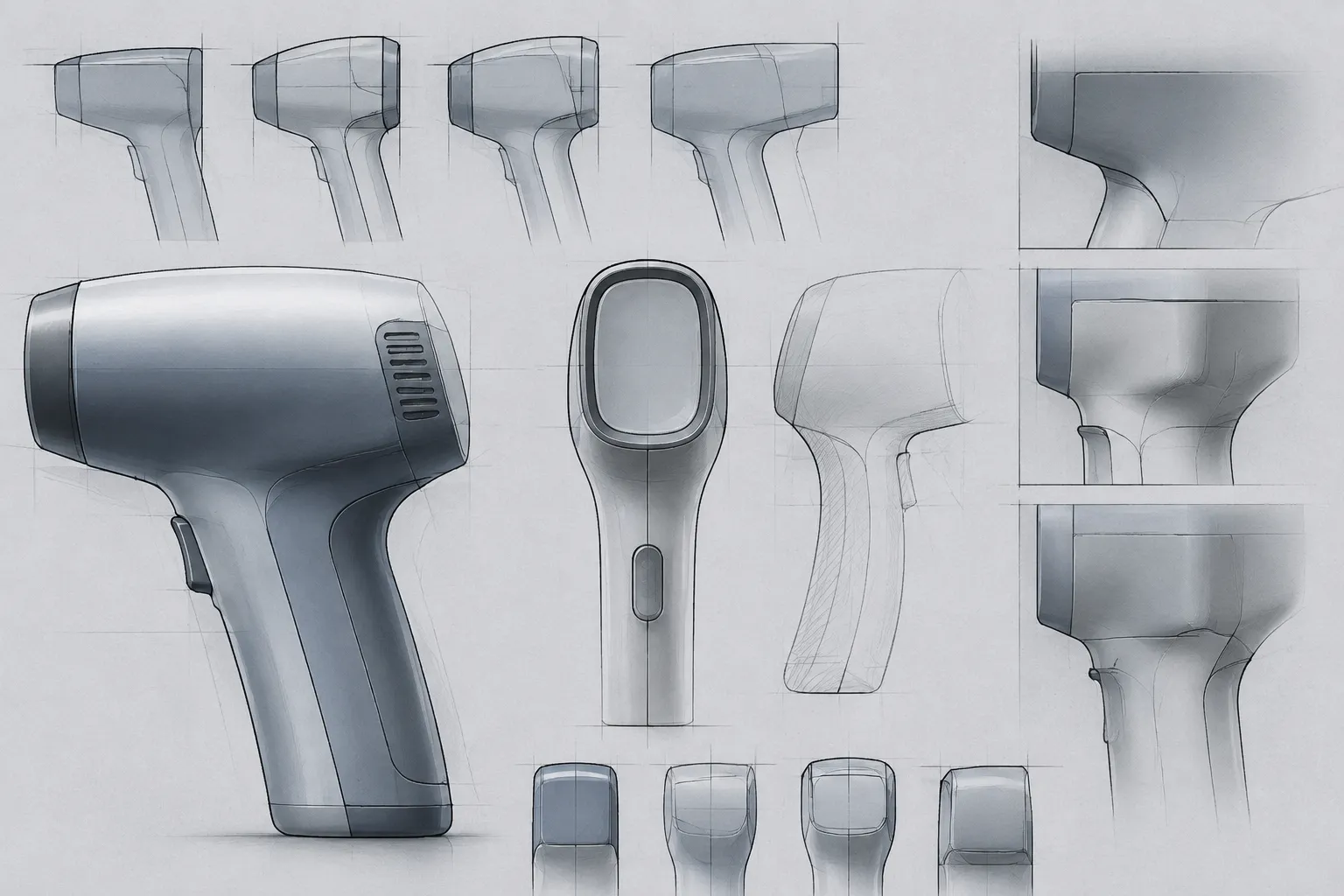
An orthographic silhouette represents a view without the same perspective convergence found in a perspective image. A perspective render introduces depth cues and viewpoint-dependent scale changes.
Direct overlay comparison becomes uncertain when one image is orthographic and the other is a perspective render. A near corner may extend beyond the expected contour, a side wall may appear narrower, and a visible top surface may change the apparent height.
You can still use both images in an early presentation review if the distinction remains visible in the record. Phrase the result narrowly:
The perspective preview makes the upper body appear broader than the orthographic study under the selected views.
This describes the representation. It does not turn an image effect into a product-property claim.
Common Misreadings
Alignment is not measurement
An aligned overlay can show relative contour differences. It cannot establish exact width, height, depth, or volume without documented geometry or physical measurement.
A clean match does not establish shared construction
Two silhouettes may align closely while their depth, internal structure, materials, mechanisms, and assembly conditions differ. The outer contour is one visible layer of the product.
An outline does not reveal hidden features
A silhouette says little about recessed surfaces, cavities, wall thickness, interfaces, or features hidden from the selected view. A missing contour detail may mean the feature is absent, concealed, or outside the viewing direction.
Inconsistent images need an explicit record
Different lenses, camera distances, viewing angles, crops, projection methods, and image resolutions can change the apparent result. When those conditions cannot be matched, preserve them as part of the comparison record instead of presenting the overlay as a neutral dimensional test.
Product categories are not evidence
An illustrative example may use a device, container, tool, or appliance because its broad form is easy to recognize. The category does not establish dimensions, use context, mechanism, or ergonomic suitability.
Record the Review Result
A useful overlay record should answer five questions:
- Which images were compared?
- What projection or viewing condition does each image use?
- What was aligned?
- Which visible differences remain?
- What requires another form of evidence?
A concise review note might read:
Direction B appears taller and less tapered in the side silhouette after baseline and centerline alignment. The upper transition remains visibly broader. These concept previews have no shared dimensional reference, so the apparent proportion change requires CAD or documented drawings before dimensional conclusions are made.
This wording separates observation from inference and gives the next reviewer a clear handoff.
When to Stop Using the Overlay
Stop when the remaining question is no longer visible in the chosen contour.
Use CAD or documented drawings for exact dimensions, section depth, interfaces, clearances, or hidden geometry. Use physical measurement when the image needs to be checked against an object. Route ergonomics, mechanisms, manufacturing, safety, compliance, and performance questions to the appropriate technical review or testing process.
The overlay has completed its role when it identifies a visible proportion difference and records the unresolved assumption behind it.
Final Review Question
Before carrying the comparison forward, ask: are the silhouettes visibly different because the product forms differ, or because the images use different projection, viewpoint, scale, or alignment conditions?
When the conditions match, the overlay can support a focused discussion of massing, height-to-width relationship, taper, feature position, and contour shape. When they do not, the comparison can still inform presentation, but the projection difference must remain part of the conclusion.
A silhouette overlay is a review instrument for visible form. It narrows the design conversation without replacing the dimensional, technical, or physical evidence required afterward.
Sources
- ISO 5456-2:1996 — Technical drawings — Projection methods — Part 2: Orthographic representations
- Extraction of product form features critical to determining consumers’ perceptions of product image using a numerical definition-based systematic approach
- A method for exploring similarities and visual references to brand in the appearance of mature mass-market products